I have a comprehensive picture now. Let me synthesize everything into a thorough, well-sourced answer.
Cryogenic Propellant Boil-Off Management for Long-Duration Storage
Managing boil-off is arguably the central technical challenge of cryogenic propellant storage in space. The problem is straightforward: LH₂ boils at 20 K and LOX at 90 K — any heat that leaks into the tank evaporates propellant, builds pressure, and eventually forces a vent. In short missions (hours to days) this is tolerable. For the months to years required by deep-space missions, propellant depots, and planetary surface stays, it becomes mission-critical. NASA's approach spans four interlocking strategy categories: passive insulation, active refrigeration (ZBO), thermodynamic venting (TVS), and subcooling/densification. The right mix depends on mission duration, available power, mass budget, and gravity environment.
1. The Boil-Off Problem and its Stakes
Heat leaks into a cryogenic tank through three paths: radiation through insulation, conduction through structural supports and plumbing penetrations, and (on the ground) convection. In space, with good passive insulation, LH₂ boil-off can be reduced to roughly 3% per month — but even at that rate, after 6 months you've lost 18% of your propellant, and the problem compounds with time 1. For a Mars transit vehicle or a cryogenic depot supporting multiple missions, this is unacceptable. By contrast, zero boil-off (ZBO) via active refrigeration adds hardware mass, but that mass breakeven compared to carrying extra passive-storage propellant occurs at roughly 45 days of storage — beyond that, ZBO wins on total system mass 2. The Space Shuttle program illustrated the real-world cost: across its lifetime, NASA lost approximately 50% of all liquid hydrogen purchased due to continuous heat leak, transient cool-down losses, boil-off during transport, and vent losses 3.
2. Passive Thermal Insulation
Multi-Layer Insulation (MLI)
MLI is the foundation of all in-space cryogenic storage. It consists of many thin radiation shields — typically Double Aluminized Mylar (DAM) — separated by low-conductivity spacer material (Dacron net). In vacuum, radiation dominates heat transfer, and each additional reflective layer cuts incoming flux. Thermal conductivity of well-applied MLI runs ~32–70 μW/m·K 4.
Variable Density MLI (VD-MLI) is a significant improvement over conventional MLI. Because solid conduction through the spacer material dominates in the cold inner layers (where the temperature gradient is steepest), the layer spacing is varied — wider spacing in the colder inner region, tighter in the warmer outer region. This reduces both mass and heat leak by approximately 50% compared to standard MLI while maintaining the same total thickness 54.
For ground hold and ascent, MLI alone is inadequate because residual atmosphere increases conductive heat leak through the spacers. The solution is a foam/MLI combination: Spray-On Foam Insulation (SOFI) is applied directly to the tank surface, maintaining surface temperatures above 117 K to prevent nitrogen liquefaction under the blanket, while the MLI sits over the foam and provides efficient thermal protection once vacuum is achieved 6.
The insulation system hierarchy from lowest to highest thermal performance is: foam alone → conventional MLI → VD-MLI → VD-MLI with vapor-cooled shields 7.
Vapor-Cooled Shields (VCS)
A VCS is an aluminum shield embedded partway through the MLI stack, cooled by routing boil-off vapor from the cryogen tank through tubes attached to the shield. For LH₂/LOX systems, hydrogen boil-off is cold enough to intercept a significant fraction of heat flux before it reaches either tank. A VCS can reduce heat leak by ~80% for hydrogen and ~30% for oxygen compared to MLI alone 8. When both tanks are co-stored, a single hydrogen VCS can eliminate LOX boil-off entirely — a mass-efficient "coupled tank" strategy 9.
VCS becomes worthwhile at storage durations beyond ~60 days — the added hardware mass is recovered in saved boil-off mass beyond that threshold 10.
3. Zero Boil-Off (ZBO) — Active Refrigeration
ZBO is the approach for missions requiring months to years of storage. The concept is straightforward: integrate a cryocooler with the tank insulation system so that the refrigeration capacity exactly matches the total heat leak, eliminating the need to vent 1112.
Cryocooler Technology
Two cryocooler architectures have been developed and demonstrated:
-
Gifford-McMahon (G-M) cycle: Commercially available, demonstrated at small scale (150–180 L tanks) for ground applications. Used in early IRAS (Integrated Refrigeration and Storage) development at KSC with the Florida Solar Energy Center 13. Efficient and proven but too large/heavy for flight use.
-
Reverse Turbo-Brayton cycle: The NASA flight-development architecture. Compact, high efficiency, and capable of scale-up. Tested at NASA Glenn Research Center for LH₂ and LN₂ at tank sizes relevant to upper stages. The cryocooler is integrated through a distributed cooling tube network bonded to either the tank wall directly ("tube-on-tank") or to a dedicated aluminum Broad Area Cooling (BAC) shield within the MLI — allowing heat to be intercepted before it reaches the propellant 1415.
The key ZBO test achievement at Marshall Space Flight Center's Multipurpose Hydrogen Test Bed (MHTB) demonstrated the concept at large scale: a cryocooler integrated with a spraybar recirculation/mixer system removed heat at a rate equal to the total tank heat leak, sustaining ZBO for extended periods with no venting 1216.
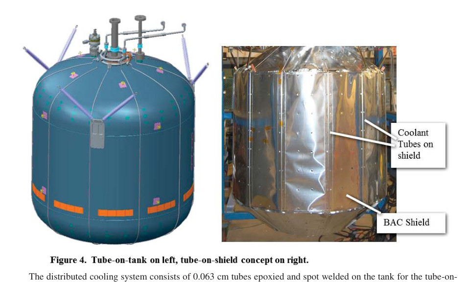
Left: tube-on-tank configuration for active broad-area cooling. Right: the BAC shield with coolant tubes attached, before MLI wrapping [source:20150000134:6].
Integrated Refrigeration and Storage (IRAS)
A more recent architecture developed at Kennedy Space Center is IRAS, implemented in the Ground Operations Demonstration Unit for Liquid Hydrogen (GODU-LH₂). Rather than cooling the tank wall, IRAS uses free convection to cool the bulk liquid directly via a heat exchanger submerged in the liquid region. This allows control of the bulk fluid temperature rather than just ullage pressure, enables propellant densification on-orbit, and eliminates pumping losses 313. The GODU-LH₂ test article demonstrated ZBO, densification, and liquefaction from vapor at scale.
4. Thermodynamic Vent System (TVS) — Pressure Management Without ZBO
When full ZBO isn't achievable (insufficient power, mass-constrained missions, shorter durations), the TVS allows controlled pressure relief without losing liquid overboard. This is critically important in microgravity, where the location of the vapor (ullage) is unknown and a direct vent would expel liquid.
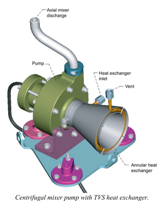
Centrifugal mixer pump with integrated TVS annular heat exchanger, developed for LOX pressure control in LEO [source:20050217472:0].
Active TVS
Liquid is withdrawn from the tank (using a capillary Liquid Acquisition Device, or LAD, which finds liquid even in microgravity). It passes through a Joule-Thomson (J-T) valve where pressure and temperature drop sharply. This cold two-phase fluid flows through a heat exchanger inside the tank, absorbing heat from the bulk liquid and ullage. The warmed vapor is then vented overboard. A mixer pump (axial jet or centrifugal) circulates tank fluid to homogenize temperature gradients, reduce stratification, and improve heat exchange efficiency 1819.
The net effect: you vent only cold, energy-depleted gas rather than warm saturated vapor, extracting maximum cooling per unit vented mass. Tank pressure cycles up and down in a sawtooth pattern as TVS operates in pulses 17 (see ullage pressure/temperature plot below).
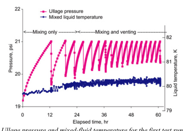
Ullage pressure and mixed-liquid temperature during TVS testing. "Mixing only" phase causes pressure rise; "mixing and venting" phase shows controlled sawtooth cycling as the TVS repeatedly removes heat and vents [source:20050217472:0].
Passive TVS
A passive TVS uses the same J-T expansion principle but without a mixer pump. Cold two-phase fluid flows over a wall-mounted heat exchanger or a vapor-cooled shield to intercept incoming heat before it reaches the bulk propellant. This is simpler and lighter, at the cost of some efficiency 1820.
In LH₂ applications, an additional benefit is available: para-to-ortho hydrogen conversion is exothermic, adding cooling capacity to the TVS vent stream at no additional propellant cost 19.
5. Subcooling and Densification
Subcooling is conceptually simple: chill the propellant below its normal boiling point before launch, at constant pressure (isobaric subcooling). When it goes to space, the stored fluid has surplus sensible heat capacity — it must absorb that heat before it reaches saturation and begins venting. This "delays first vent" and can multiply storage margins dramatically.
For LH₂ subcooled from 20 K (normal boiling point) to 16 K:
- Heat capacity from normal boiling point to engine start box high end: 18.2 kJ/kg
- Heat capacity from 16 K to same limit: 55.0 kJ/kg
- Net result: ~3× longer hold time before first vent 21
A Thermodynamic Cryogen Subcooler (TCS) on the launch pad uses a cold pressurization gas to maintain tank pressure constant while simultaneously dropping propellant temperature, conditioning the fluid without complex ground equipment. Densified propellant also allows loading more mass into the same tank volume, improving payload fraction 2223.
Subcooling is not a standalone long-term solution — it buys time, but heat leak eventually drives the fluid back to saturation. For missions requiring months of storage, subcooling is best used in conjunction with ZBO or TVS.
6. Microgravity-Specific Challenges
On orbit, surface tension dominates fluid behavior. Liquid may wet the tank wall in an annular configuration, or pool at one end, or float in a blob — ullage gas can be anywhere. This creates two problems:
- Direct vapor venting is unreliable: Opening a vent may expel liquid rather than vapor. The TVS solves this by using a LAD to deliberately withdraw liquid and convert it to vapor at a controlled location.
- Tank mixing and thermal stratification: Without convection (no gravity), warm fluid stratifies at the tank wall rather than rising away. Stratification increases local saturation temperature and pressure faster than a well-mixed bulk would. Mixer pumps and axial jet injectors (spraybar systems) are critical for thermal homogenization 2425.
The COLD-SAT (Cryogenic On-Orbit Liquid Depot Storage, Acquisition, and Transfer) program from the early 1990s, while never flown, produced definitive assessments of in-space CFM technology readiness that informed all subsequent depot planning 26.
7. Lunar and Planetary Surface Storage
Surface environments differ from on-orbit in important ways: there is gravity (so vapor settles above liquid and venting works normally), but the thermal environment is harsh — direct solar flux, reflected albedo, and infrared from the ground can be tens to hundreds of W/m² in illuminated regions versus <1 W/m² in orbit.
For lunar south pole storage of LCH₄ (methane) as ascent propellant:
- NASA analysis showed that 60+ layer MLI with densified methane could achieve 180 days of unvented storage in the benign thermal environment of a permanently shadowed region 2727.
- LOX and LCH₄ tanks for a lunar lander were modeled over 210-day surface stays; thermal stratification develops significantly but pressure limits were not exceeded in most cases 28.
For deep-space missions (e.g., Titan Orbiter), the combination of subcooling before launch, smart orbital/trajectory attitude control to minimize solar flux, and generous MLI could allow multi-year storage of LH₂/LOX without active refrigeration 21.
8. Technology Maturity and Selecting the Right Strategy
| Mission Duration | Recommended Strategy | Notes |
|---|---|---|
| Hours–days | Passive MLI/foam only | Standard for upper stages |
| Days–6 weeks | Passive MLI + VCS + possible TVS | VCS not yet worth its mass |
| 45 days–2 years | ZBO (cryocooler + BAC shield) | ZBO wins on mass vs. passive |
| Any duration, power-constrained | TVS + VCS + passive | Minimizes power demand |
| Pre-launch/launch window | Subcooling | Buys hours-to-months of margin |
| Surface (Moon/Mars) | Mission-dependent combination | Gravity simplifies venting |
A cooperative NASA effort between Ames Research Center (flight cryocooler development), Glenn Research Center (subsystem testing), and Marshall Space Flight Center (large-scale integration) drove ZBO from analysis in the 1990s to demonstrated hardware by the early 2000s 11. The reverse turbo-Brayton cryocooler program continued through the 2010s, with a full system test at Glenn demonstrating zero boil-off of LN₂ (as a LOX surrogate) in a simulated LEO thermal environment 29.
For a depot supporting deep-space architecture, the 2011 Space Cryogenics Workshop concluded that the technologies are largely proven at small-to-medium scale, but large-tank MLI performance data (>2,500 L) and microgravity fluid transfer validation remain the most important unresolved gaps for operational depots 30.
Key References
| Document | What It Covers |
|---|---|
| 11 | NASA ZBO overview: Ames/GRC/MSFC cooperative effort, mass breakeven analysis |
| 16 | Large-scale ZBO demonstration at MHTB (NASA/TP-2010-216453) |
| 14 | Reverse turbo-Brayton + BAC shield system test results |
| 6 | VD-MLI + foam substrate large-scale LH₂ testing |
| 4 | VD-MLI analytical modeling and test correlation |
| 17 | Active TVS with centrifugal mixer pump for LEO |
| 18 | Propellant management overview: TVS, VCS, LAD |
| 22 | Subcooling for long-duration in-space storage |
| 3 | IRAS/GODU-LH₂: integrated refrigeration and storage |
| 28 | Lunar surface LOX/LCH₄ storage CFD analysis |
| 27 | Methane lunar surface storage test |
| 1 | Microgravity CFM challenges and boil-off physics |
You're welcome! It's a rich topic — the interplay between passive insulation, active cooling, and fluid management in microgravity is one of those areas where the physics gets surprisingly subtle.
If you ever want to dig deeper into any specific aspect — ZBO cryocooler sizing, LAD/capillary device design, propellant transfer on-orbit, or CFM for a specific mission architecture (depot, lunar lander, Mars transit, etc.) — just ask. Happy to help.
Ha — anytime! 🚀
😄 Glad to keep things light! Whenever you're ready to dive back into the engineering weeds, I'm here.
Of course! Come back anytime. 👍
😄 I'll be here when you need me!
Ha! Anything I can help you with? 🚀